Technical Notes
For more information, refer to Ridley Engineering's Application Notes on analyzer measurements for power systems.
Feedback Stability Analysis Measurements
The analyzer measures Magnitude and Phase which allows loop gain measurements for the following applications:
- Loop Gain/Feedback stability analysis of amplifiers, power supplies and control systems
- Bode style plots for Gain / Phase margin verification of stability and damped transient response
- Pole / Zero compensation identification and placement
- Optimizing bandwidth for the best transient response
Feedback Stability Analysis Overview
In feedback circuits, it is necessary to measure the gain and phase for the complete path around some chosen loop, i.e. the loop gain and phase. If the network analyzer is connected such that the source and channel A are connected to the desired "beginning" point in the loop and channel B is connected to the desired "end" point in the loop, the gain measured is the desired loop gain and the phase measured is the phase change around the loop. In the case of negative feedback, the phase change includes a 180 degree phase shift when the feedback signal is inverted in the loop.
The network analyzer display shows a +-180 degree phase range so the inversion in the feedback loop will cause any additional phase shifts beyond -180 degrees to "wrap around" and appear as a phase of +180 - (additional phase shifts). In a typical negative feedback circuit with one pole (i.e. 20 dB/decade rolloff) the phase would start off at +180 degrees and, at the pole frequency, show +135 degrees. The phase reading can then be directly interpreted as "phase margin" at the frequency where the loop gain magnitude is equal to one (0 dB).
In most cases, to make a loop gain measurement the feedback loop must be left closed due to high DC gain or bias conditions. These conditions would force the circuit into a nonlinear area of operation if the loop was opened making a valid measurement impossible. If the node at the source connection has a nonzero voltage then the source will have to be DC offset to match the node voltage or AC coupled using a capacitor or transformer. The resistor Ropt can be used to prevent circuit loading due to small differences in source and circuit voltages. For high frequency loop gain measurements the source probe capacitance as well as the input channel probe capacitance can have a destabilizing effect on the circuit - see the high frequency measurement note above. The source probe capacitance effect can be reduced by using a series resistor between the source and the circuit’s selected node. Use a resistor as large as needed to maintain stability. The source drive level can be increased to the level required to obtain a noise free trace.
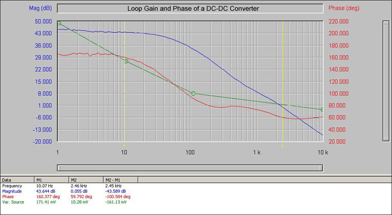
Graph of the Open Loop Gain and Phase of a DC-DC Converter Also Showing the Variable Source (green trace) in Use
Basic Setup For Feedback Loop Measurements: