

Technical Notes
For more information, refer to Ridley Engineering's Application Notes on analyzer measurements for power systems.
Frequency Response Measurements
The Frequency Response or Analog Network Analyzer can measure Magnitude and Phase which allows measurements for the following applications:
- Filter characterization including Insertion loss, passband and stopband frequencies
- Component characterization including impedance and resonant frequencies
- Bode style plots for loop gain/feedback stability analysis of amplifiers, power supplies and control systems
- Bandwidth of input and output stages
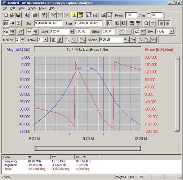
Graph of the Frequency Response of a 10.7 MHz Bandpass Filter
Basic Setup:
The analyzer has two input channels for ratioed, transfer function measurements.
To obtain a circuit's transfer function, the analyzer's source and channel A are connected to the circuit's input node while channel B is connected to the circuit's output node.
The source signal, which provides the stimulus for the circuit under test, can be injected into the circuit either directly or AC coupled using a transformer. The frequency sweeps can be either logarithmic (for Bode type plots) or linear.